Skin On Frame Kayak
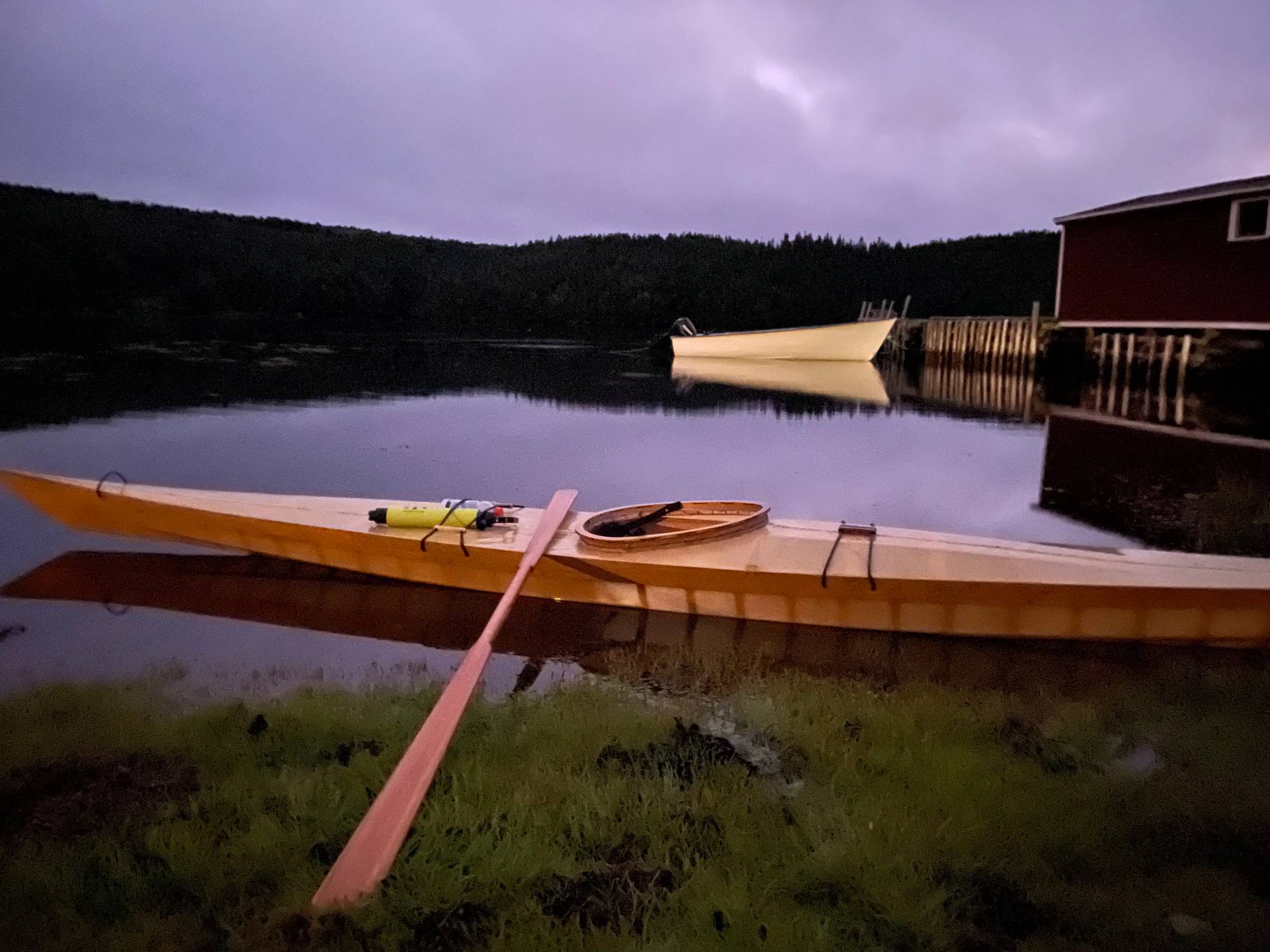
This post describes the build process and thoughts for future improvements of a skin on frame kayak. 6 years later I am still using it regularly and it has been an excellent performer. The boat was christened in Washington state, used many summers in Ontario and was brought to Newfoundland for a summer where it finally tasted salt water and was used almost daily.
I did not start with the idea of building a kayak, it went through a few evolutions. My girlfriend at the time had a project in second year university to build a boat out of cardboard and duct tape. I thought this sounded like a very fun idea, and had some thoughts about how I would go about building it. I was talking about this with a friend and we decided we should just build our own. This got slightly out of hand and our ambition grew. Instead of building a small boat, we would build a full sized boat out of cardboard and duct tape and float down a river near where we were living. We then said to ourselves “If we’re going to build a full sized boat, we might as well make one that will last. It won’t be much more difficult”. This launched a roughly year long saga.
Major Frame Members
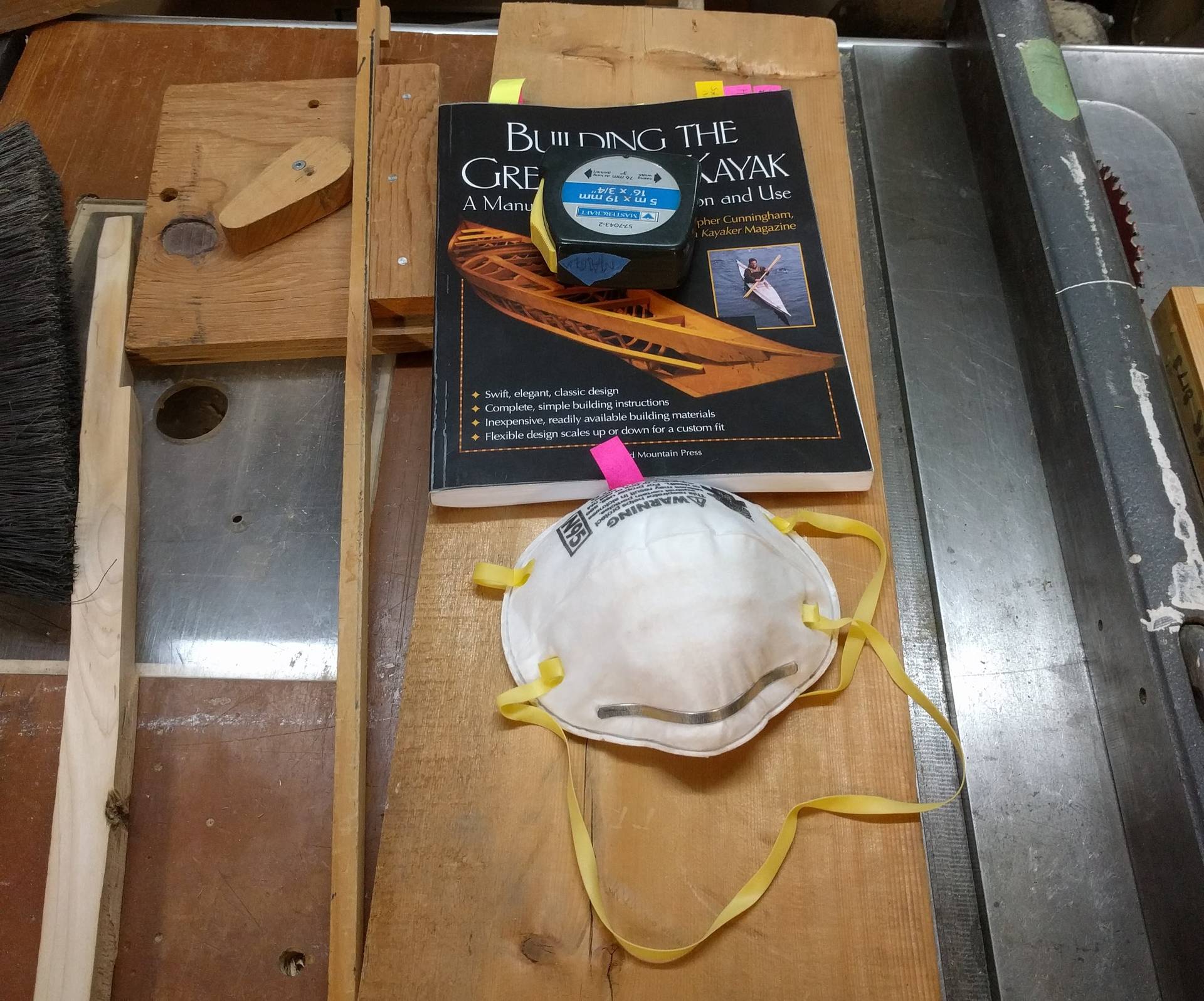
That evening we ordered “How to Build a Greenland Kayak” by Chris Cunningham off of Amazon. Less than a week later we were doing the several hour drive to my parent’s place to stay there for a week during reading week and build some boats. We studied the book while driving. I was fortunate to grow up being taught woodworking by my dad, who has a well equipped shop in the basement.
We started by scrounging in the garage for all the material required. We had a number of suitable pieces of maple for some of the larger deck beams (Masic), Cedar from an old fence and various pieces of pine for the bow, stern and less structurally important deck members.
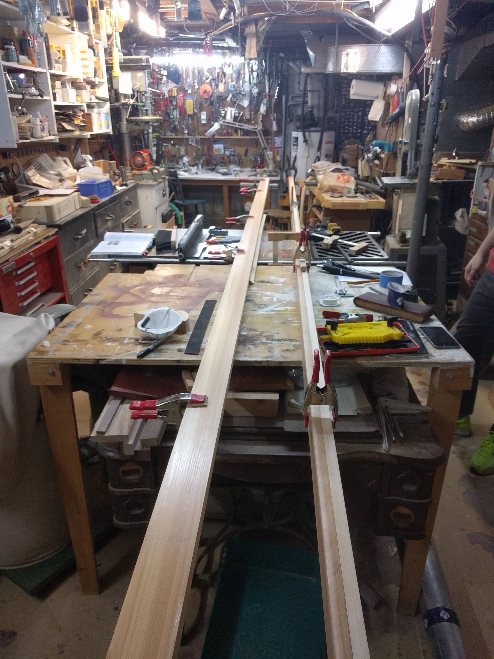
Some of the specialty wood, such as a 16ft by 0.75 inch by 12 inch piece of clear, straight grained Cedar was no just lying around. The cedar is for the gunnels, chines and keel. You don’t need a 12inch wide section as you will be cutting them down to widths of 2.5inch (2pcs), 0.75 inch (4pcs), and 1 inch (1pcs) respectively. It is however very important that the stock is of the highest quality because this will directly translate to the quality of the boat. Thankfully Ottawa has some great specialty wood stores so we were able to pick up everything required. We also got a clear straight grained 2x4 by 8ft piece of Douglas fir for a paddle, and ash for the ribs and cockpit coaming. The ash was unfortunately already kiln dried so it did not steam bend very well, but we muddled through.
We then visited a local leathermaking store and picked up the Latigo leather strips required for the deck fastening and the waxed nylon for the lashings.
With all the purchases out of the way, it was time to get started. Our initial goal was to complete the frames within the week when we had access to all the tools. I find the kayak fascinating because it does not require any power tools or a huge shop, but having access to this certainly makes things easier.
The first step was to cut down the long cedar sections into the gunnels, chines and keel as mentioned above. The main planning happens in the gunnels. Here you lay out where the ribs are going to lie and where the deck beams are going to lie. You start by building two jigs for the ends of the gunnels that will hold them at the correct angle and spread from the middle. At each deck beam location, you can now measure and rough cut your stock before more precisely fitting it. As with any boat building you are always working with compound angles and doing your best to keep things fair. Sighting became more important than measuring and it was a process to relearn how to woodwork. What you are seeing in front of you becomes much more important than the dimensions on the drawing.
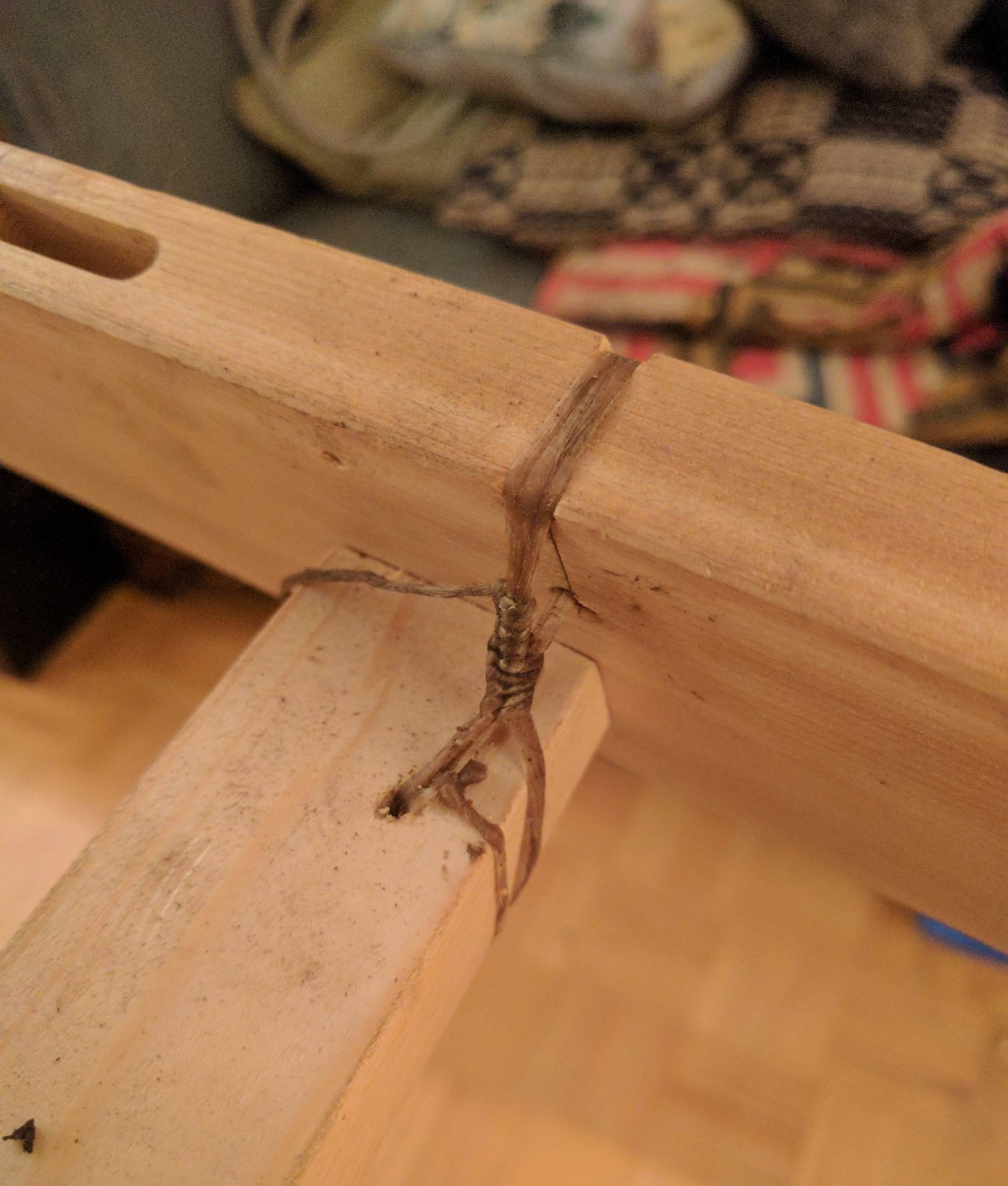
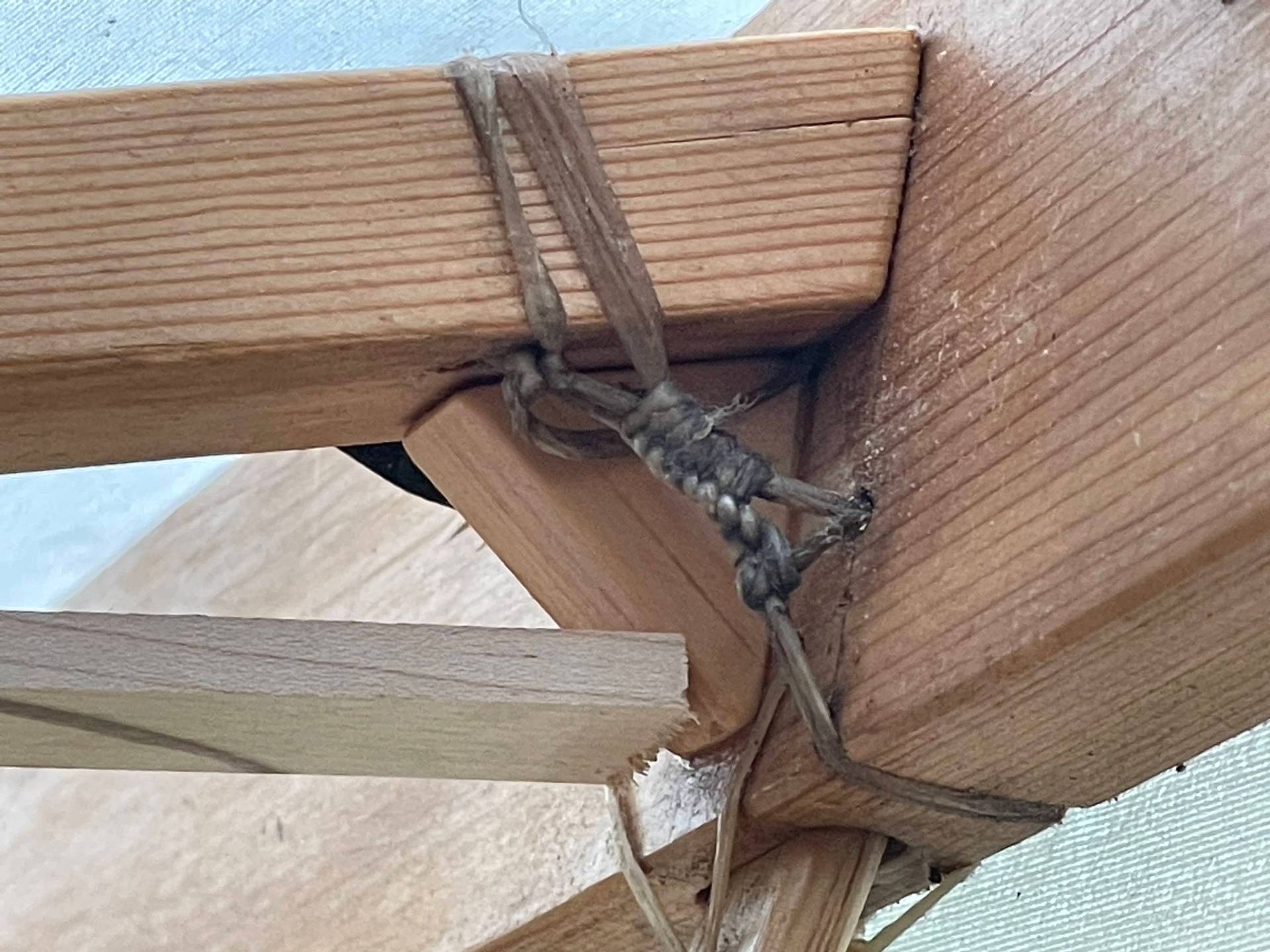
There are many ways the deck beams could be attached. These small decisions occupied a large amount of time during the build process. If there was an experienced boat builder at our disposal it would have saved a lot of time, but as it was we just had to do the best we could. We decided to use two dowels installed at angles. The angle prevents the beam being joined from being able to directly pull out. The end of the dowel is split and a narrow wedge was inserted before it is fully seated. This causes the end to expand when the wedge is hammered in, thereby locking the dowel in the hole. It’s very important to make sure that you are paying attention to the grain direction here. The wedge provides tremendous mechanical advantage and can easily split the gunnels. To further keep the deck beams from pulling out they are lashed in which pulls them down and tighter to the gunnels. The tight wrapping of the skin helps to keep the gunnels from spreading apart and also helps keep the pins from working their way out.
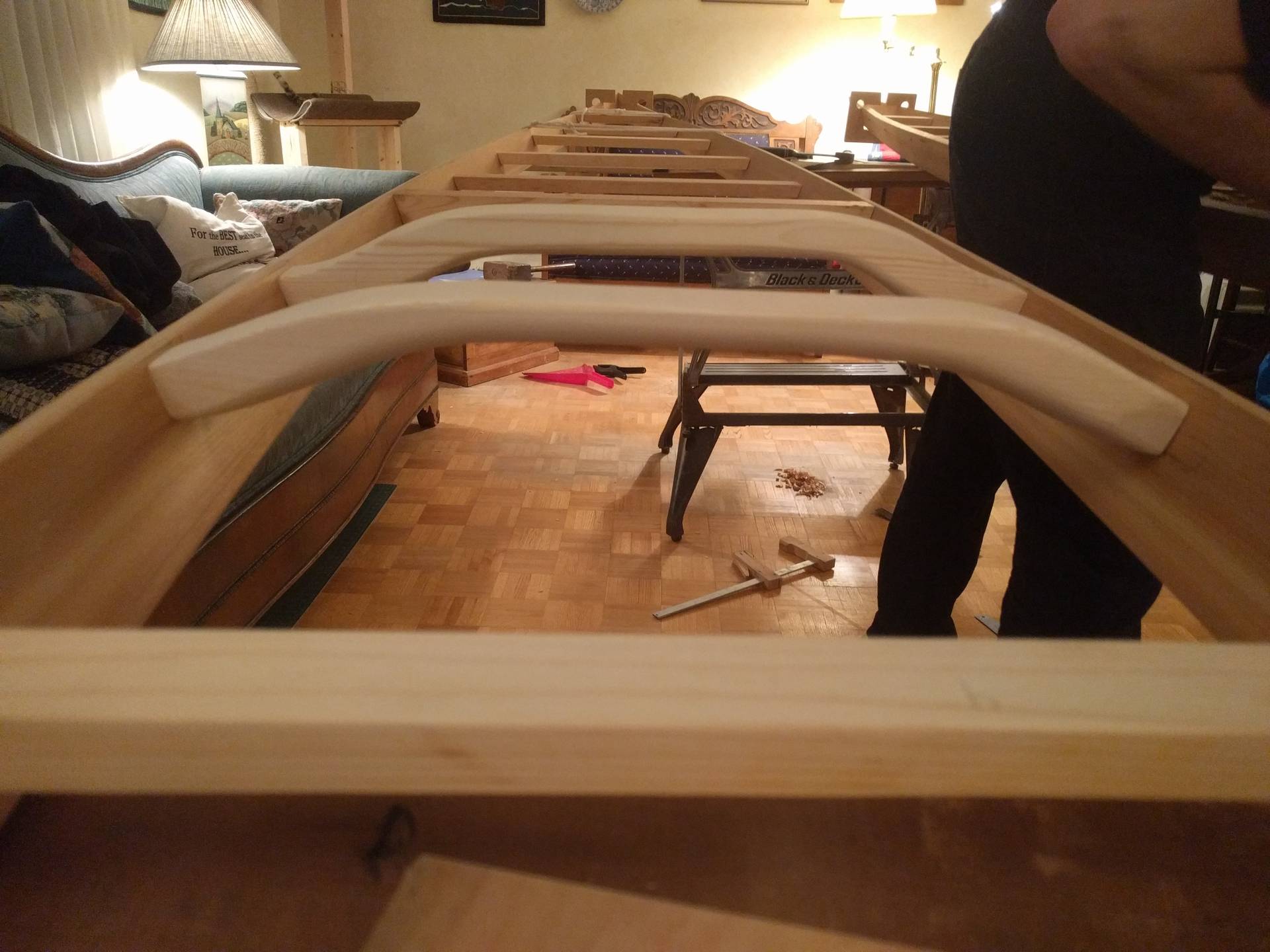
One of my main gripes is the location of the deck beams. When touring the internal volume of the kayak is very small. Instead of having the beams near the center of the gunnels, I would move them closer to the top and keep them slightly curved. This would not change the actual internal volume of the boat but would make it infinitely easier to pack. The current location of the beams interferes with trying to shove gear into the boat. Additionally slightly curving them would improve the ability to shed water, particularly on the bow. I have had a few instances where the boat has started to submarine. Keeping the deck relatively flat is nice for gear storage. It is a pain to reach into the boat for gear while you are on the water.
One of the main themes in the skin on frame kayak is the lack of glue, screws or nails throughout the entire build. This, combined with the skin that remains pliable allows the entire boat to flex to absorb and dissipate shock. In theory, this allows the build to be lighter while remaining sufficiently strong versus a similar rigid design. There are of course a few places where I cheated here. Firstly, I epoxied on some skegs at the bow and stern to provide a little more rub protection. Secondly, when entering and exiting the kayak you sit on the deckbeams immediately aft of the cockpit. I epoxied on some reinforcing gussets to the gunnels. The weight of your body puts a large load on the dowels holding the deck beams on. These gussets are only glued to the gunnels, so the flexibility is retained but they are still close enough that when you sit on the deck beams they can settle on the gussets and transmit the load directly to the gunnels. More about this modification can be found towards the end of this post.
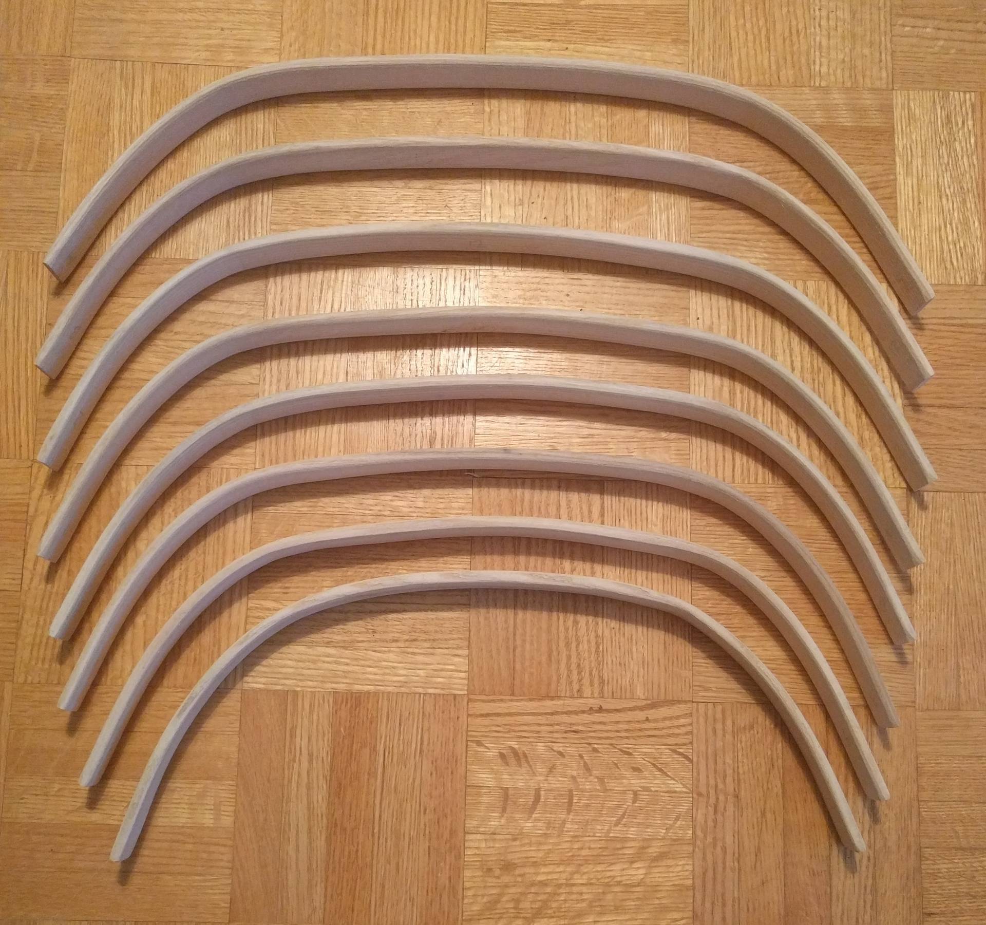
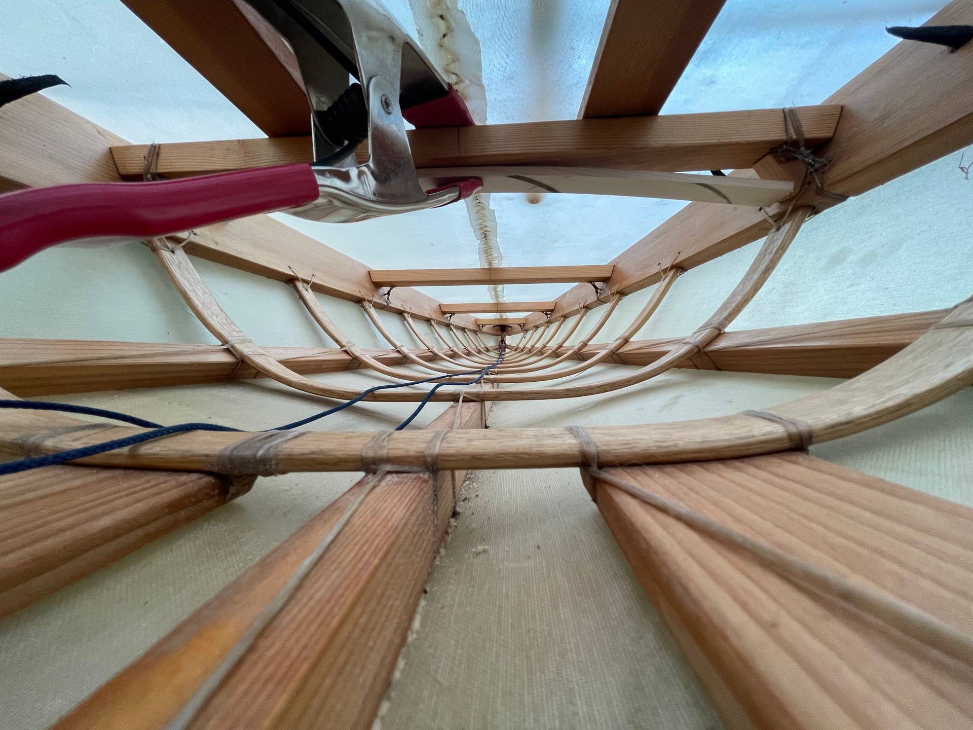
After the deck beams are installed it is time to start on the ribs. The first step is to prepare all the stock to width, and then cut it to length. The book provided formulas for lengths that would provide a fair curve. We repurposed a kettle and some ducting to build a steaming rig. Steaming was fun as you had to work quickly so there was no overthinking, only instinct. Thankfully it’s a small penalty if you ruin a rib and need to restart. The tight curves near the bow and stern were particularly challenging. In the end, I had to thin out the section to be bent. Pockets for all the ribs were routed into the gunnels before the installation of the deck beams which made it very convenient to fit the ribs as you are working. Thin dowels (bamboo skewers) were used to hold the ribs from falling out. In theory, the skin would be sufficient to prevent this, but it seemed very prudent to have some positive retention. We also lashed the ribs in, this I would say is not required if you are also pinning them. If I had to choose I would take a lashing over a pin any day. Pins are weaker, weaken the wood around them and are more liable to work their way out. They are however quicker to install.
The transom and bow are made with solid planks of pine. This is another aspect of the design I am not sure about. Even with holes cut in the plank, they are heavy. The grain is not in a great orientation so I think it is quite weak, and this seems like a major deviation from the Greenland designs. It is however important to get adequate volume in the bow and stern. I’d like to spend time studying other designs to come up with some alternative suggestions.
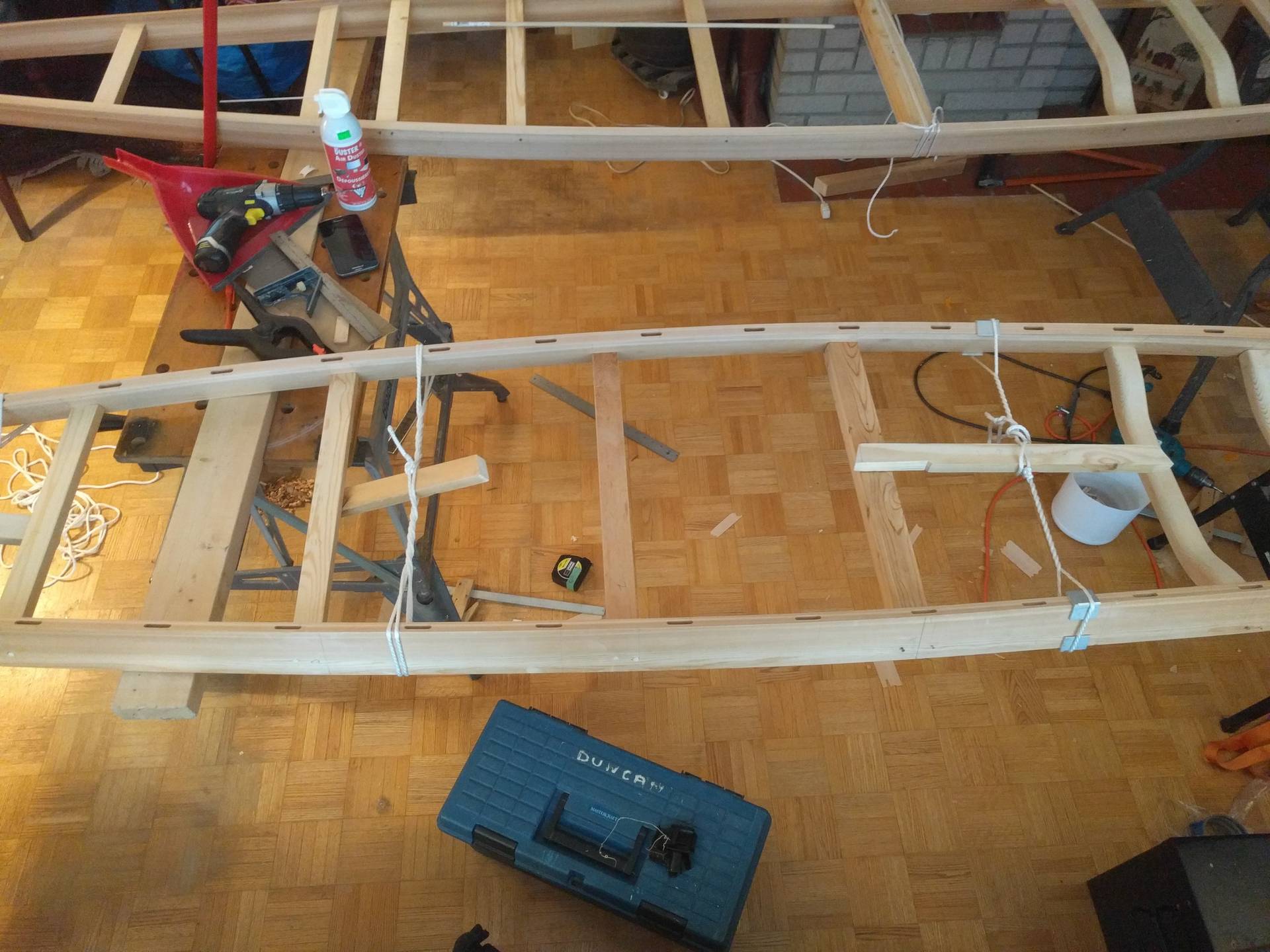
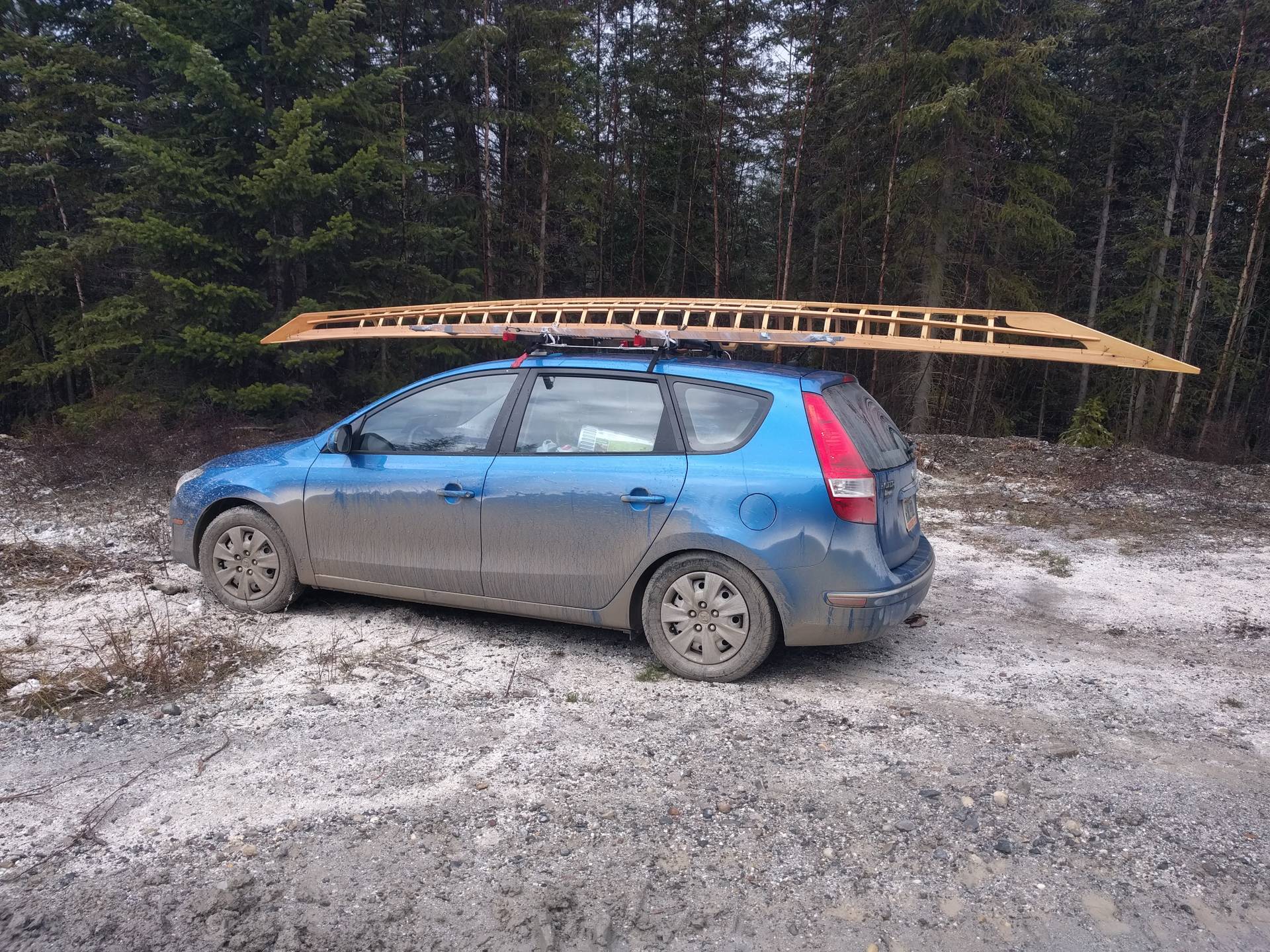
With the exception of the coaming these are the major frame structures, and the major woodworking complete. Excellent timing because the week was up and it was time to return to University. With literally only an inch to spare we were able to manoeuvre the semi completed frames out of the living room and strap them on the car. The chines and keel were not installed, nor were the ribs pinned and lashed so we could disassemble the frames and easily transport everything.
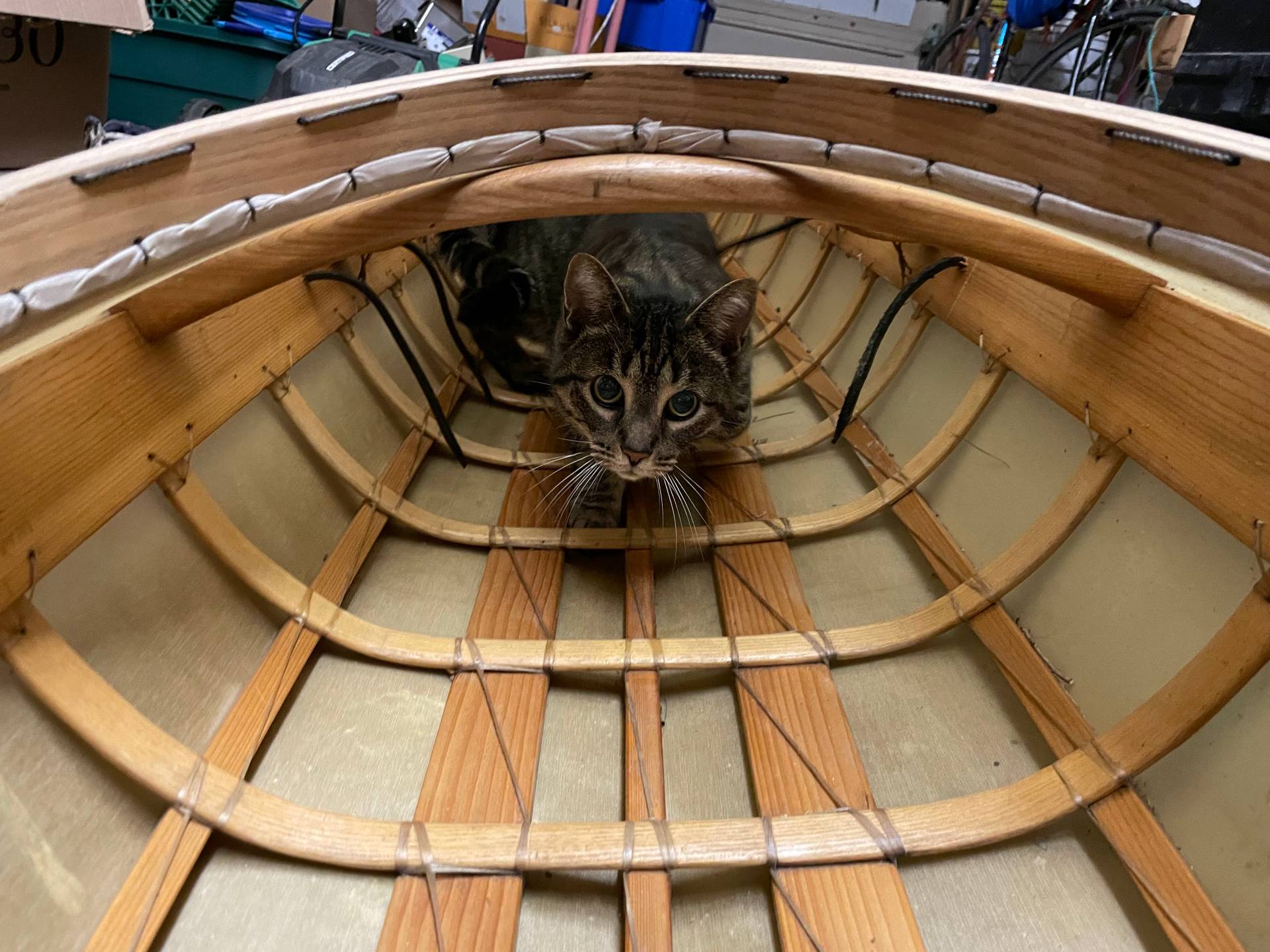
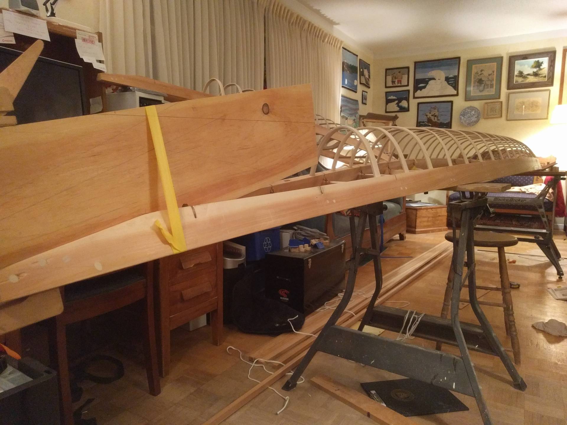
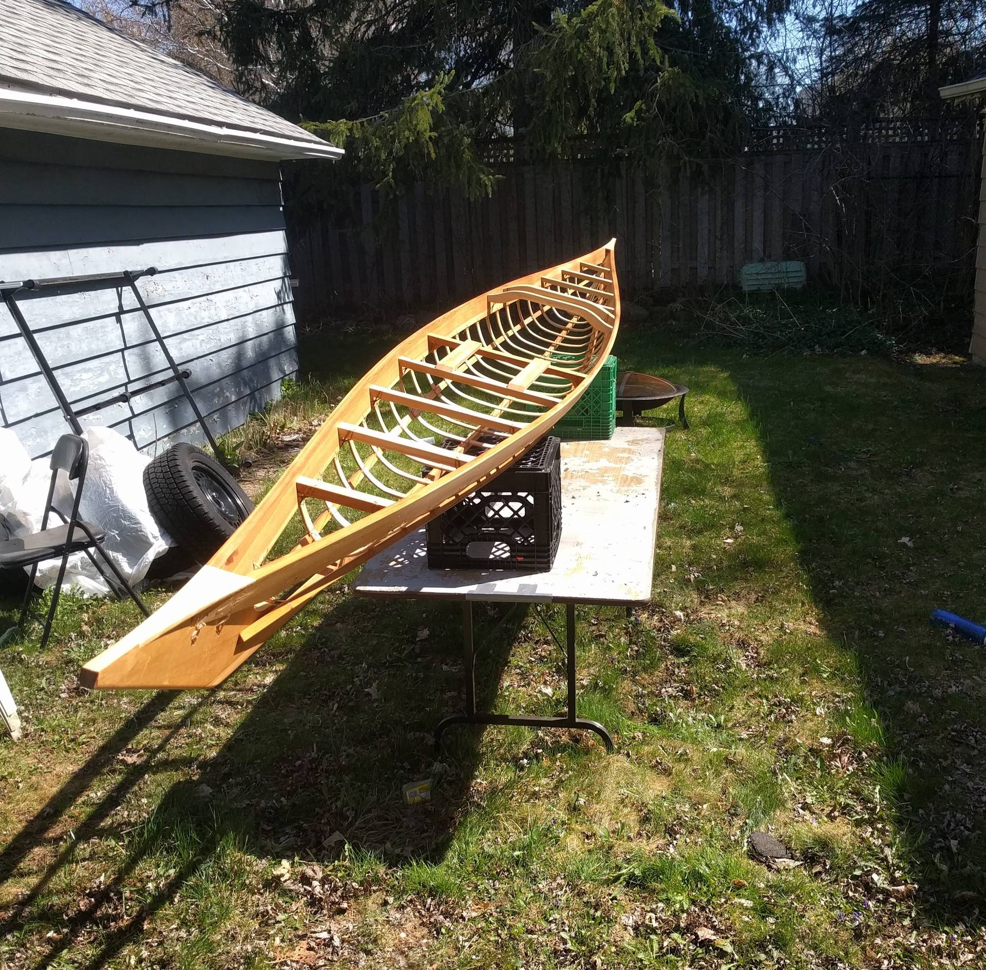
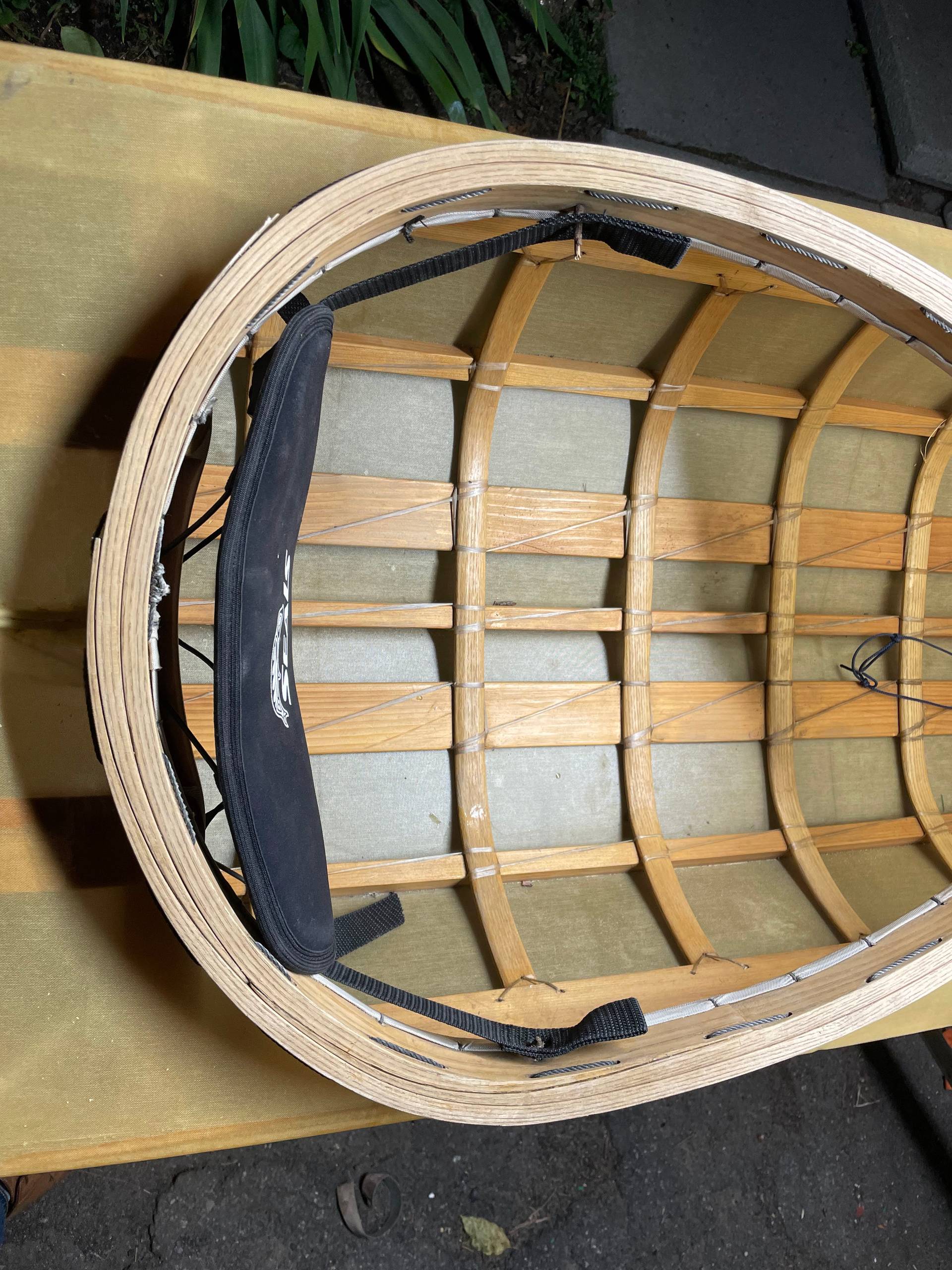
Completed Frame
Over the next few weeks, I picked away at small bits and pieces while studying. Come exam time I got more serious with the build (and the procrastination from studying) and completed the frame. The keel and chines are lashed on with the help of a series of fairing blocks. I think that ideally you would not want to use any fairing blocks as if you are accurate with your rib bending you will end up with a fair hull. Regardless I made sure with the help of a bedsheet to visualize the shape I was going to end up with a pleasing hull. At this point the project was very “real” and I spent quite a lot of time sitting in the half completed frame pretending I was paddling.
The final step on the frame was to apply several coats of tung oil to help preserve it. The material choice of primarily cedar means that there should be good rot resistance naturally, but making sure the boat remains dry while in storage is something I am very careful about. As the frame will be covered with a skin and will not be accessible there are not any opportunities to reapply. Tung oil remains slightly flexible and has good penetrating properties so it is preferred to varnish in this use case which is quite brittle and can crack.
It was now the spring of 2017 and I had an internship in Vancouver. A friend and I decided to road trip so I again put the frame, now complete, on the roof of the car and drove the several thousand kilometers out.
Skin and Final Details
I was working at General Fusion and they were gracious enough to allow me to use tools after hours and store the boat on premise. People were very excited about the project and encouraging. I still had a paddle to make, the coaming, and sew and coat the skin.
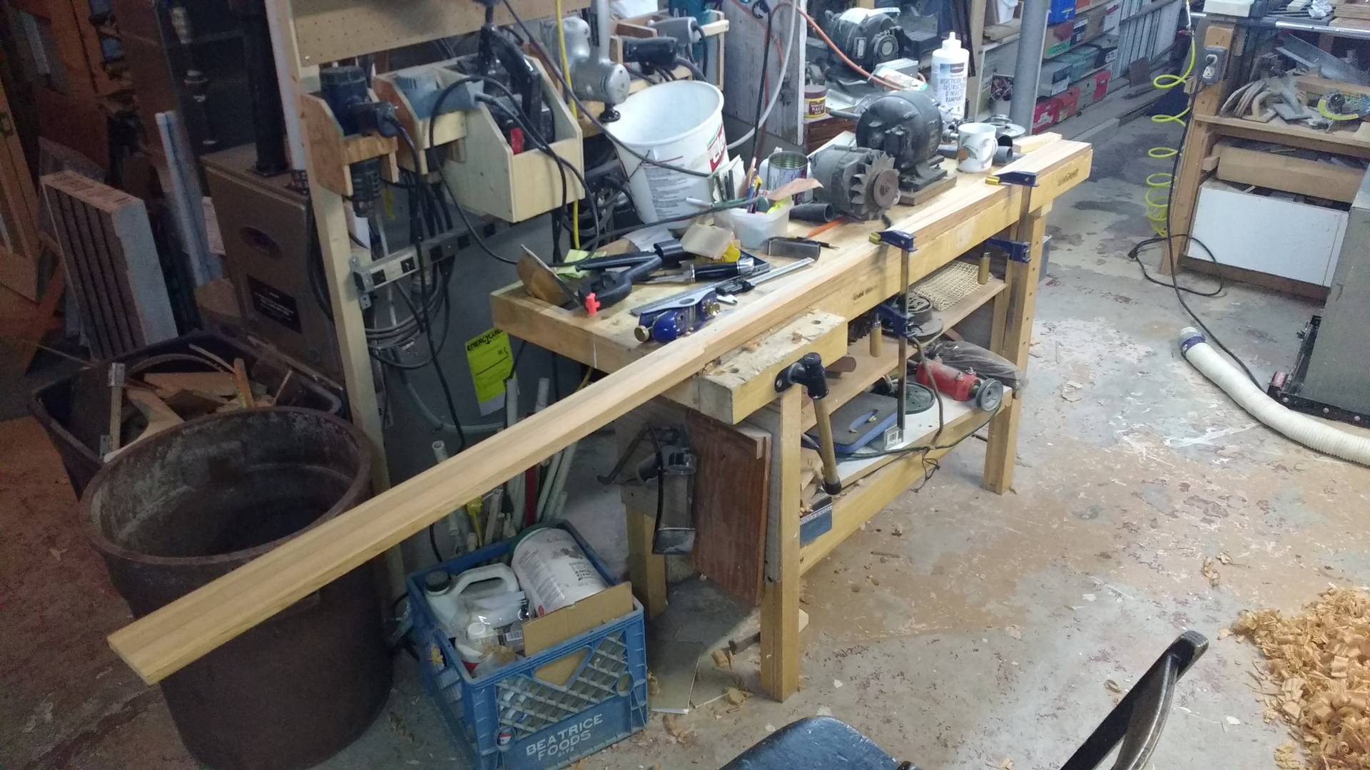
The paddle was much more straightforward woodworking. The entire paddle can be made from a single 8 foot long 2 by 4 (from a specialty wood store, so actually 2 inches by 4 inches). Although at first glance the paddle appears to be oddly proportioned given the very long and narrow blades it proves to have a sufficient wetted surface, is light, well balanced, and opens the opportunity for different strokes. The basic proportions are scribed out and the bulk of the material is removed with the help of a band saw. The cuts are taken down to the line with a plane before the second set of lines are drawn.
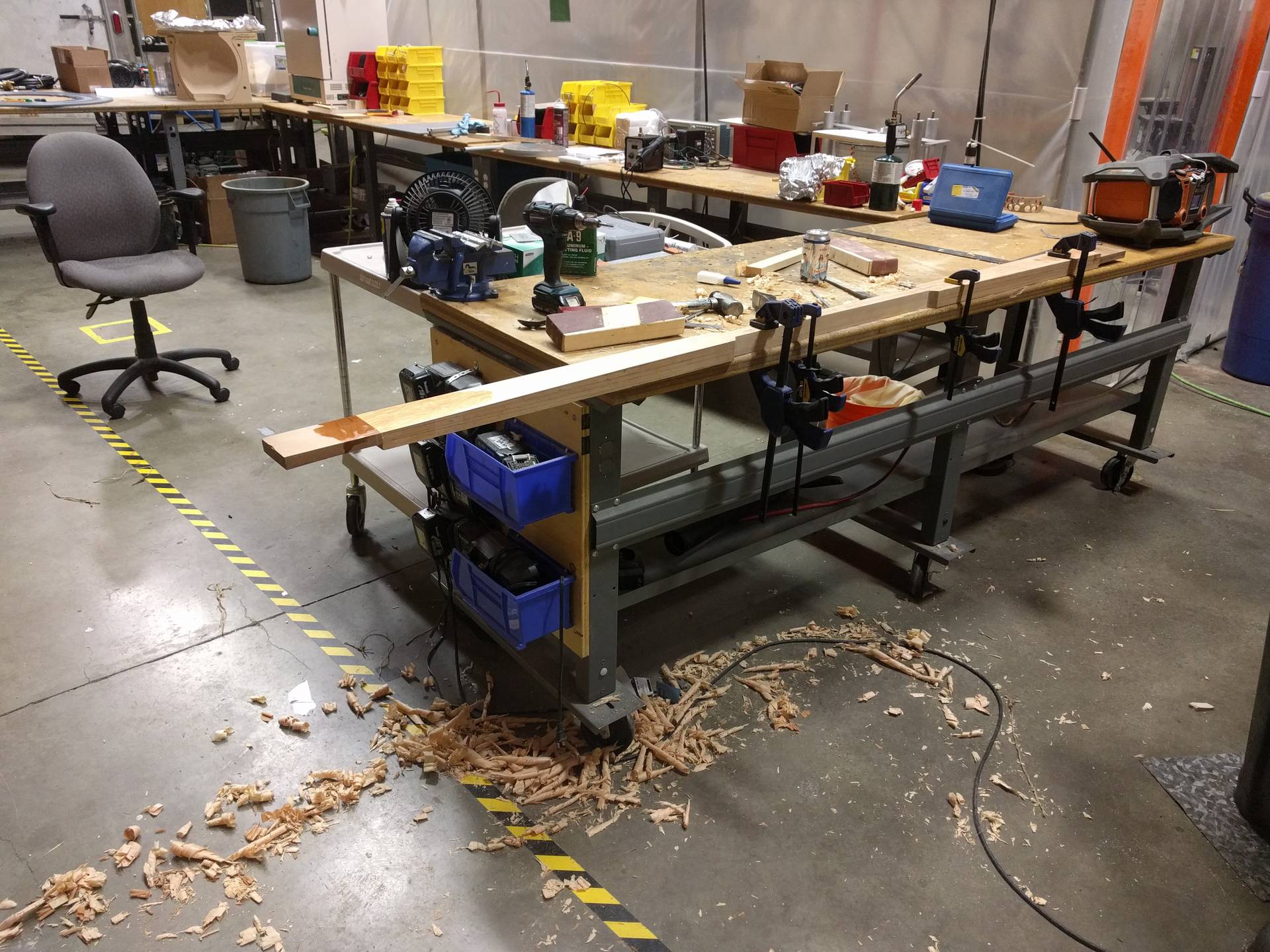
From here it is mostly plane works to gradually coax the boxy shape into smooth lines. The only real challenges are maintaining fair surfaces and good transitions between the blades and the handle at the center. The shoulders in particular require extra care. I ended up building two paddles, the first out of Douglas fir with cherry tips, and the second out of cedar. The book recommended orienting the grain of the protective tips perpendicularly, but I cannot recommend this as this leaves them very weak. The lightness of the cedar paddles is simply unbeatable and I far prefer this one. If I were to make another one, I would build it out of cedar and attempt steam bending a thin strip of a hardwood (approximately 2-3 feet long, 1/4inch wide) as a rub strip and visual relief. The cedar paddle has taken some knocks and abuse over the years.
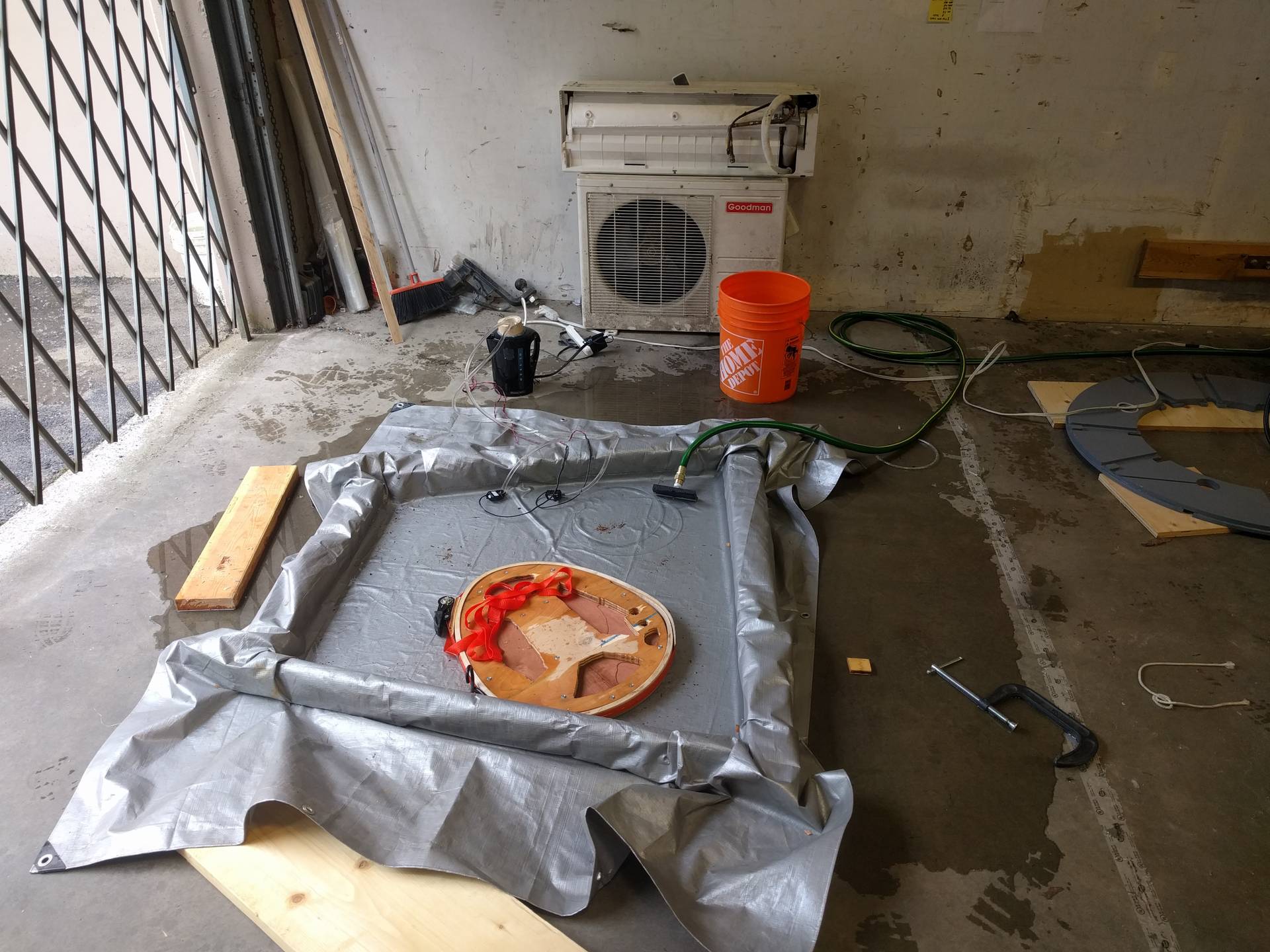
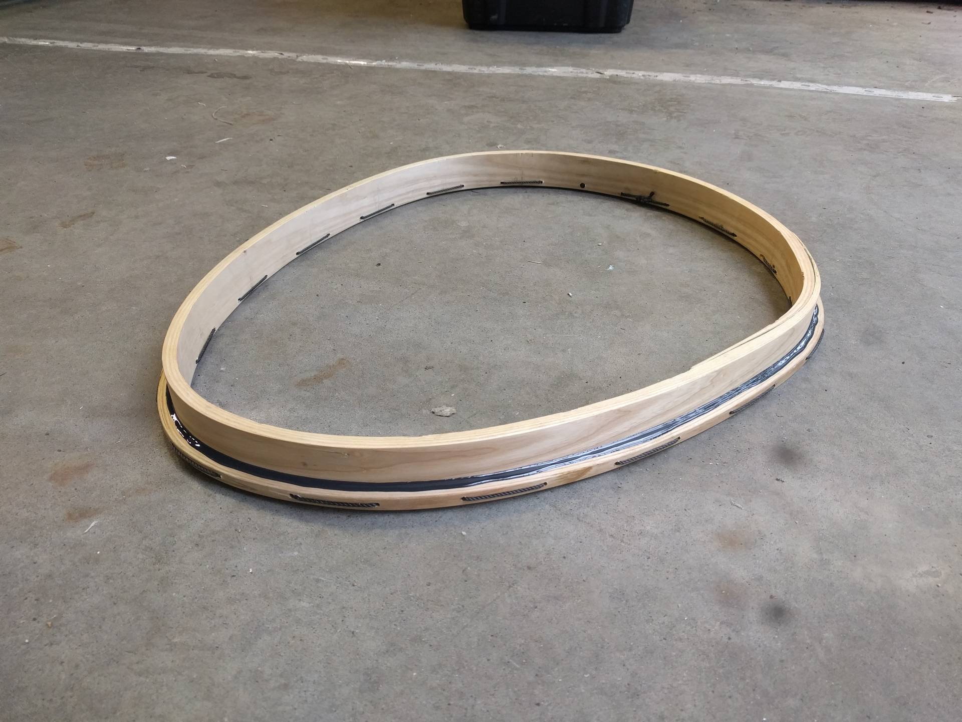
The coaming was the last major woodworking project and was a bit annoying to complete. It required some relatively tight bends and I no longer had access to the steaming setup used for the ribs. Instead of attempting steaming, I opted instead for a hot water bath. Maintaining sufficient temperatures to properly soften the lignum would prove to be slightly problematic. I bought a kettle from Value Village and drilled a hole in the bottom to which I glued a straw. I set up a large shallow bath with a few 2x4s as walls and a tarp. Using an aquarium pump I was able to pump water from the bath back into the kettle. When the water level in the kettle is high there is more hydraulic pressure so it will flow out quicker. When the water level is low it will flow out slower. This means that the system is someone self balancing and I only need to turn it on and cut the length of the straw (shorter means lower friction and faster discharge) to roughly match the output of the pump. Given that the kettle was only 1500 watts and the heat dissipation due to evaporation and conduction into the ground for such a large surface area is very significant I could only maintain around 60c. This was certainly better than nothing, and the large bath allowed me to perform the bending little by little but I still ended up with cracks on the tightest radius. I made liberal use of epoxy to take care of this.
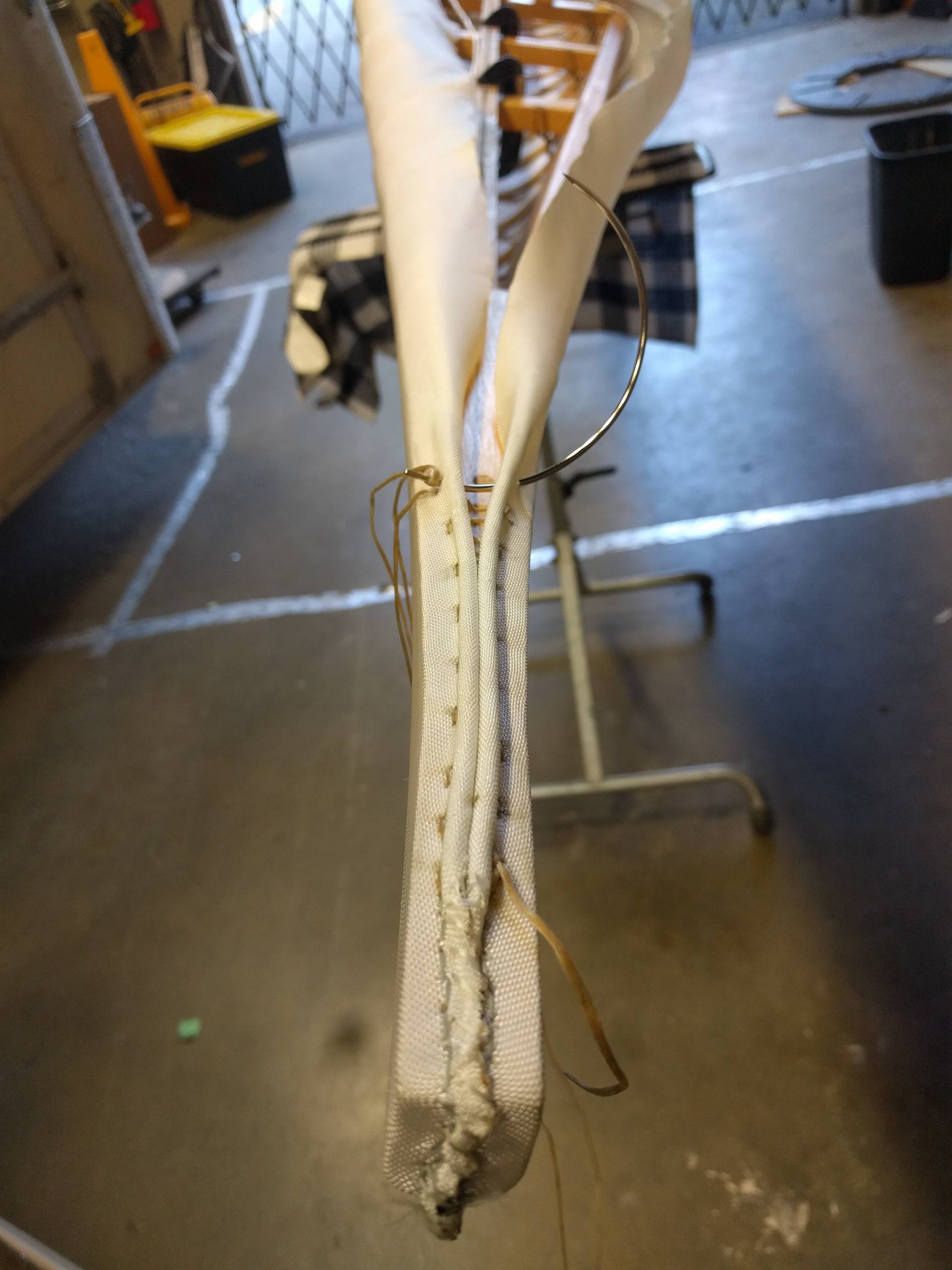
The sewing of the skin was something I was nervous about, but is in fact quite quick and easy. I turned a custom tip for my soldering iron on the lathe so I could have a hot knife to make fray-free cuts. The skin is carefully pinned in place to check alignment before being zippered up and sewn shut. The instructions call for wax free dental floss to be used as the thread. The absence of wax means that the coating will stick to it. However, when working I found the floss was breaking constantly so I switched to the same artificial sinew used on the rest of the boat. Foam rod was used as spacers to help maintain a cleaner and straighter seam. The main challenge here is in the straightness of the seam, as from where you sit in the cockpit you are in the perfect position to eternally admire any mistakes you made.
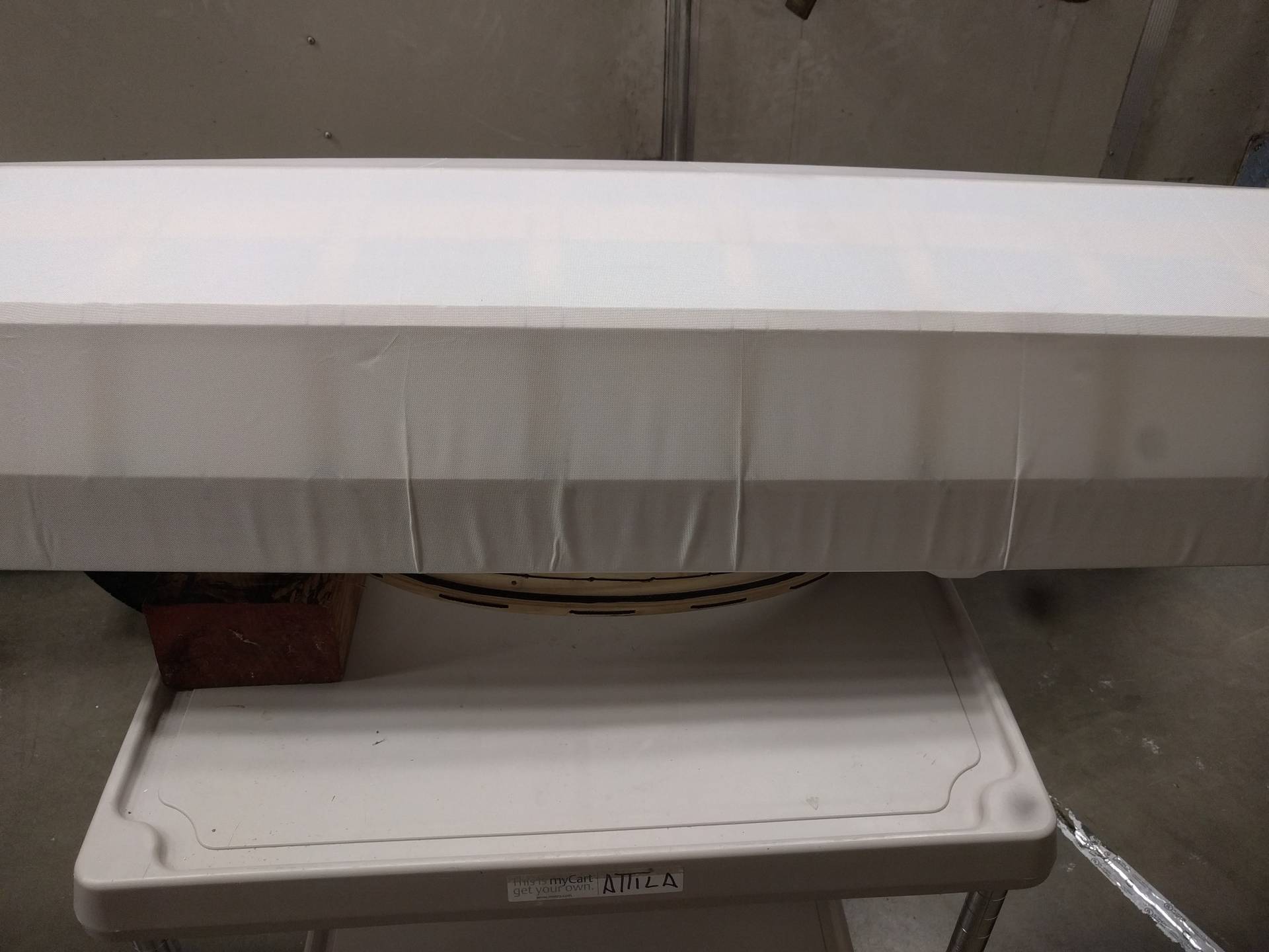
A thin layer of two part polyurethane epoxy is then applied to the skin to seal it, harden it and provide some ultraviolet resistance. This was again daunting, but in the end straight forward. My only issue is that I would have preferred a slightly longer working life and I felt that the epoxy had started to harden while I was still applying it. Additionally, I was slightly too liberal with my application and had a few drips.
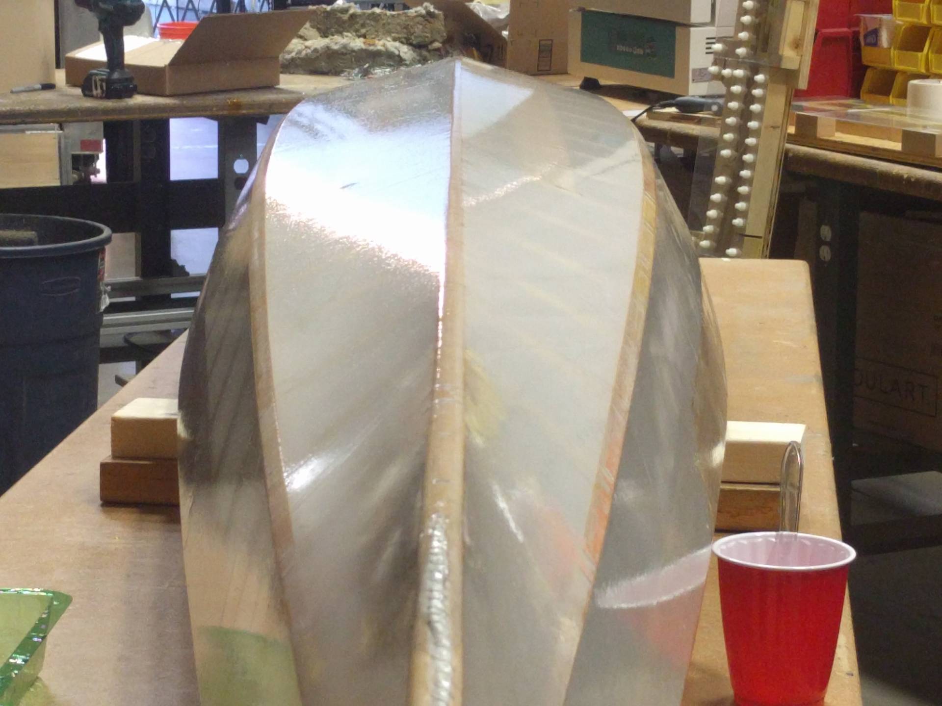
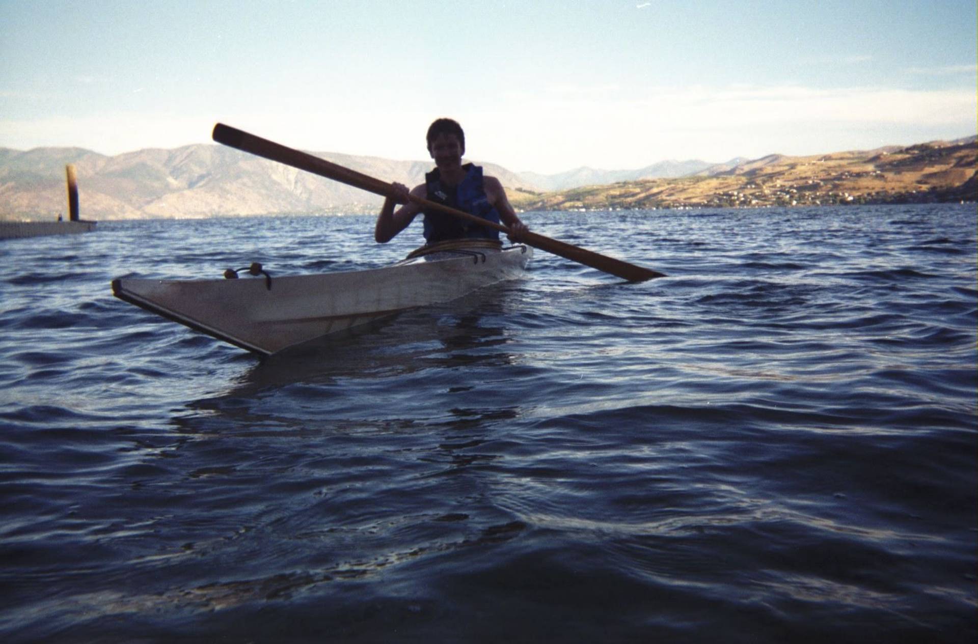
With the kayak now complete it was time to try it out - the perfect opportunity presented itself when returning from Vancouver in Lake Chelan, Washington. The water was warm and crystal clear.
Modifications
After now 6 years of ownership, I have made a few modifications.
Strengthened deck beams aft of the cockpit
To enter the kayak you sit on the deck just aft of the cockpit. These were making some unpleasant noises and flexing each time I would sit. The deck beams run perpendicular to the centerline of the boat and transmit the load to the gunnels by two relatively small dowels on each side. I was worried about shearing these dowels, or worse, splitting out the ends of the deck beams. Once the epoxy is applied to the skin there are not many good options for major internal modifications, so I wanted to avoid anything breaking.
I approached this problem by making gussets that I could epoxy to the gunnels just below the connection to the deck beams. I only applied epoxy to the connection between the gusset and the gunnel and left the joint with the deck beam dry. This allows the boat to still flex, but when load is applied to the deck beams they move sufficiently to sit on the gussets and transfer the load to the gunnels via the gussets, and not the potentially weak joints.
More comfortable cockpit
I found the cockpit to not be very comfortable to start, but with three modifications it is quite good now.
First, a back support was installed. This wraps around your back and provides much better lumbar support, while still being small and unobtrusive.
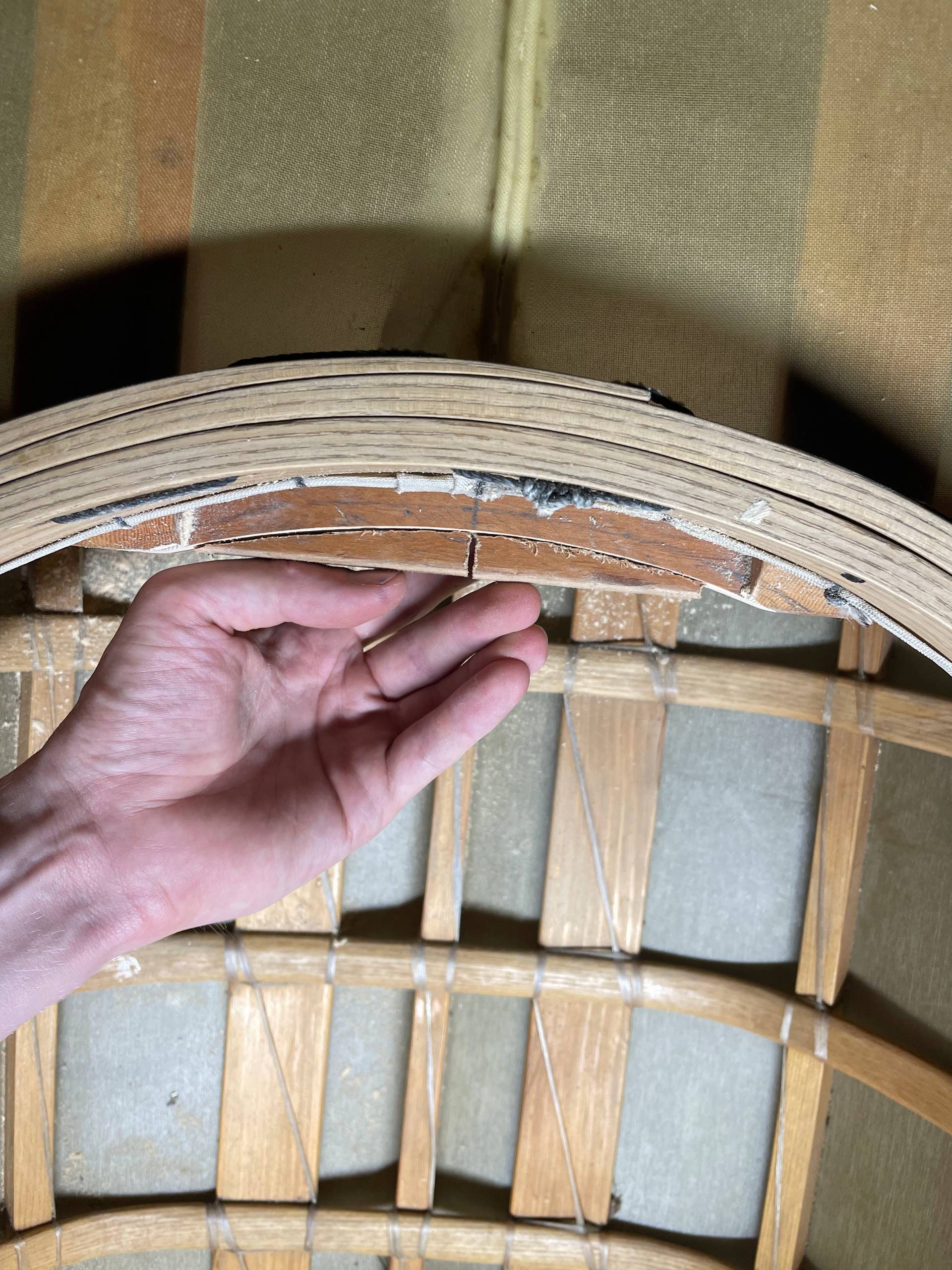
Secondly, the deck beam that your back would normally hit was cut away to be curved. This slightly increased the size of the cockpit which was surprisingly beneficial. Additionally, it increases the surface area where your back rests reducing hot spots. As I was concerned about removing material in this critical area I made a similar sized stiffener and epoxied it to the aft of the deck beam.
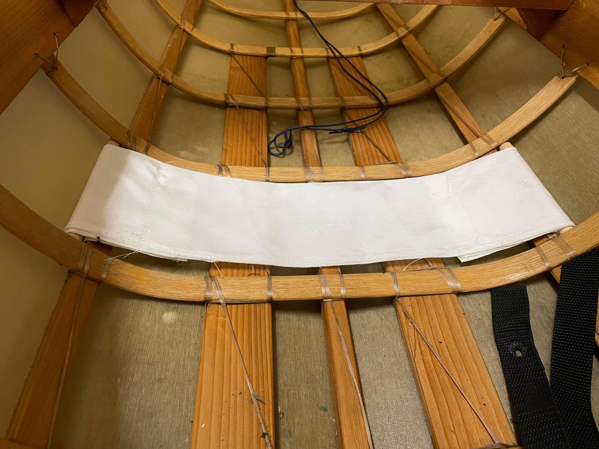
By design, you are intended to sit directly on the bottom of the boat. This is great because it lowers your center of gravity and therefore keeps you stable. This does have the disadvantage that the keel and ribs will cut off your circulation and quickly become uncomfortable. I used foam pads for a while but was never fully satisfied with them. A thin towel also works but can slide about and quickly become annoying. Cape Falcon kayaks had suggested a cloth seat that is suspended from the chines with a pair of dowels. It holds you similar to a hammock without pressure points, and if constructed properly (IE the right length) just barely raises you off of the floor of the boat so your center of gravity is not unduly affected. I sewed one up using spare nylon from the skin. I can confirm that it is very effective.
Storage
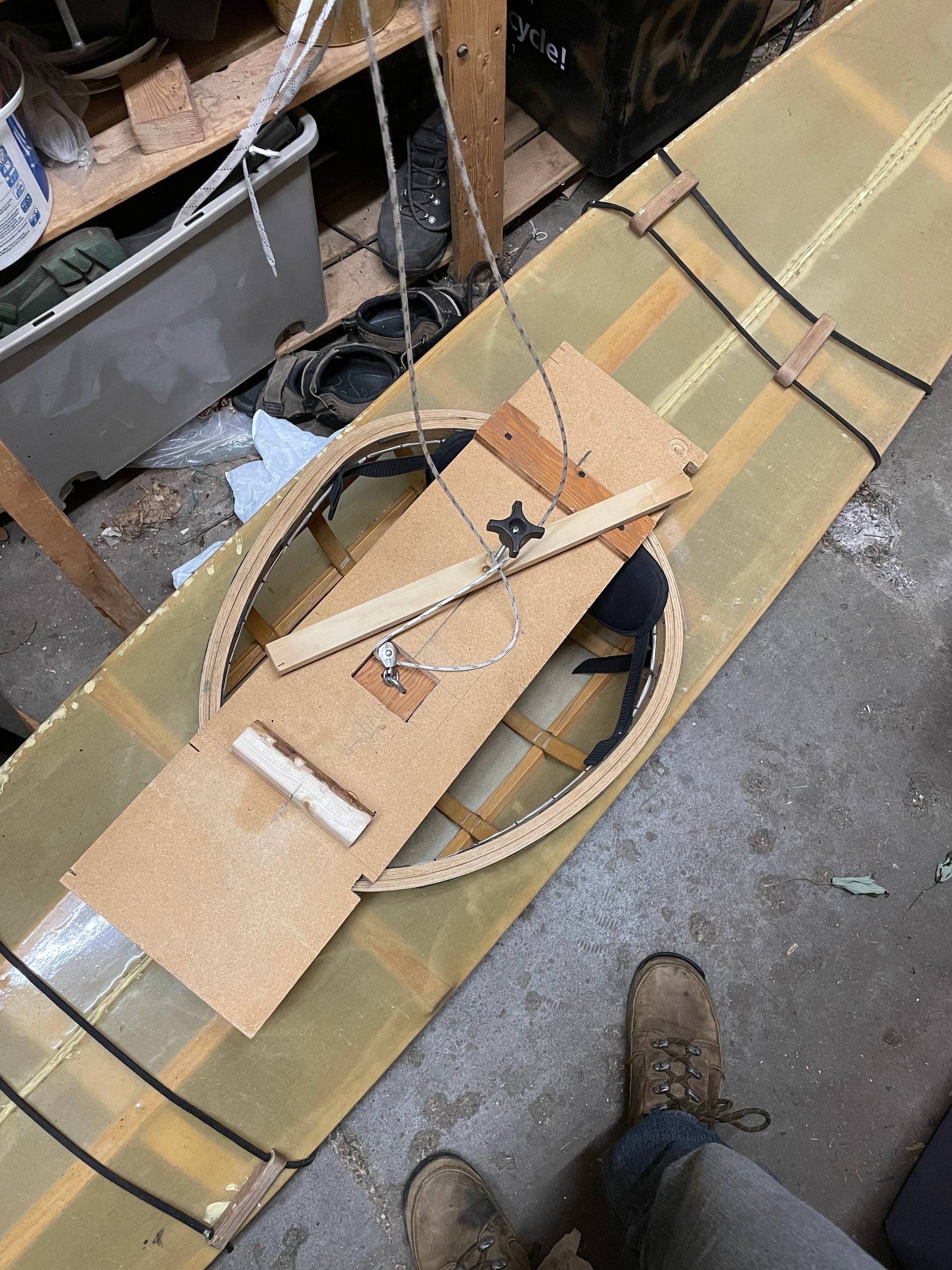
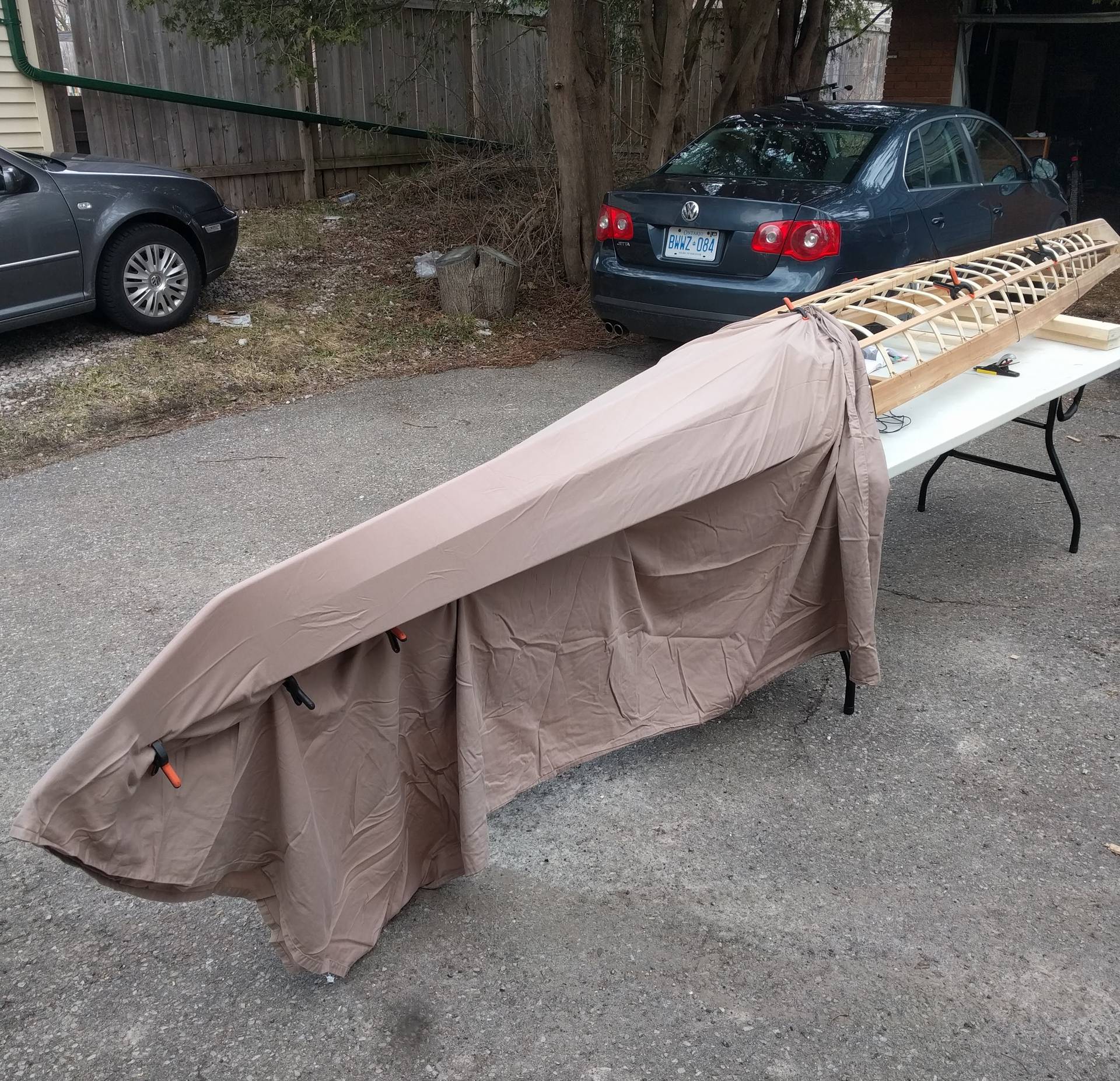
The lifetime of the boat can be greatly extended with proper storage. This is ideally indoors, but can be tricky for a 17 foot boat. Additionally, you don’t want the storage to be so cumbersome that you find yourself too lazy to take the boat out on a whim because it is too much of a hassle to get ready.
A good solution here was a balanced beam that could be clamped into the cockpit, and then a pulley system that allows you to quickly hoist the boat for out of the way storage on the ceiling.